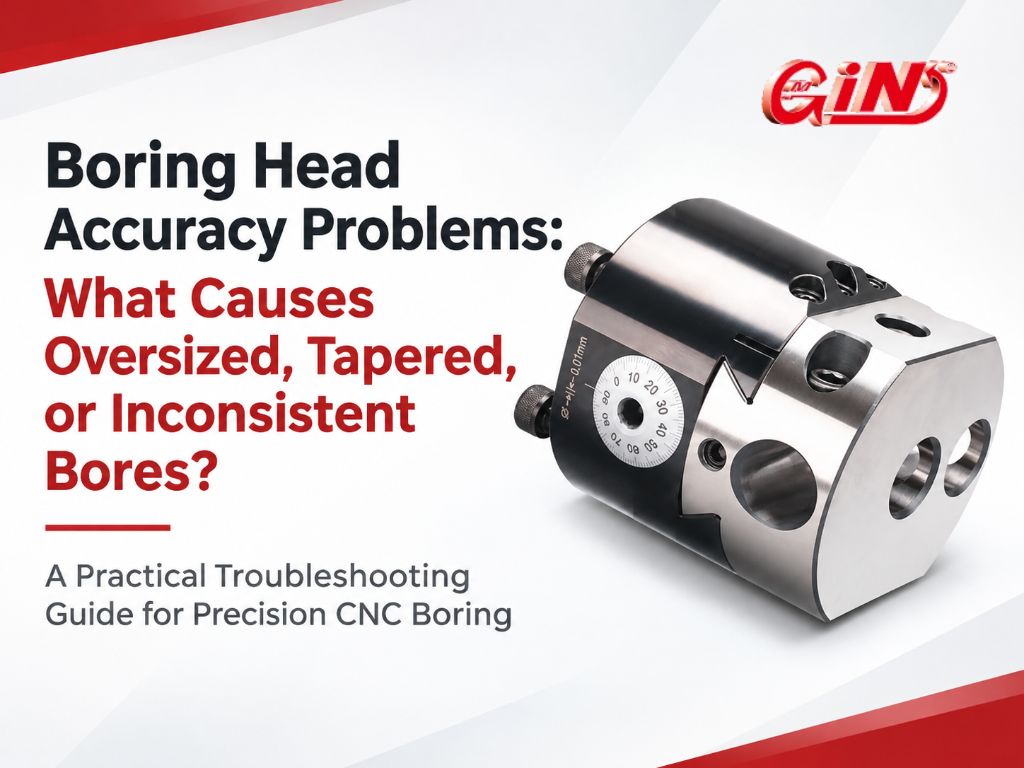
A Practical Troubleshooting Guide for Precision CNC Boring
When a CNC boring operation produces oversized, tapered, or inconsistent holes, the first step is to identify the dimensional error before adjusting the boring head. An oversized bore may result from an incorrect diameter setting or cutting-edge movement, while a tapered bore can indicate tool deflection, alignment problems, or changing cutting forces. Diameter variation between parts may point to thermal drift, tool wear, or inconsistent setup conditions.
This guide explains how to identify each problem, measure the bore correctly, and determine whether the solution requires a machining adjustment, a tooling correction, or a more suitable fine boring head.
1. Quick Diagnosis: What Does the Bore Error Tell You?
The shape and consistency of a bore error provide important clues about its cause. Before changing the tool offset or boring head setting, compare the measured hole dimensions with the required tolerance.
| Bore Problem | Likely Causes | First Action |
|---|---|---|
| Oversized bore | Incorrect diameter setting, tool movement, thermal effects | Verify the setting and measure the finished diameter |
| Undersized bore | Tool deflection, wear, insufficient stock removal | Check the cutting edge and remaining stock |
| Tapered bore | Bar deflection, alignment error, uneven cutting load | Measure diameter at several depths |
| Diameter changes between parts | Thermal drift, tool wear, inconsistent setup | Compare results across consecutive parts |
| Different diameters around one cross-section | Out-of-roundness, vibration, measurement error | Measure at multiple angular positions |
A bore may exhibit more than one error simultaneously. For example, a hole can be oversized at the entrance and undersized near the bottom.
2. Why Is the Finished Bore Oversized?
An oversized bore occurs when the measured hole diameter exceeds the specified upper tolerance limit. However, an oversized result does not automatically mean the boring head itself is defective.
Incorrect Diameter Adjustment
A common cause is setting the cutting edge too far from the spindle centerline.
On a single-point boring head, the radial position of the cutting edge determines the nominal cutting diameter. Because the tool cuts on both sides of the rotating path, a radial adjustment changes the diameter by twice that amount.
For example:
- Radial adjustment: 0.005 mm
- Corresponding diameter change: approximately 0.010 mm
Always check whether the boring head's adjustment scale indicates radial movement or diameter change.
Cutting-Edge Movement
If the boring tool or insert shifts during cutting, the actual cutting diameter may differ from the intended setting.
Inspect the insert seat, clamping screws, boring bar mounting, and connection between the boring head and shank. Follow the tooling manufacturer's tightening instructions.
Thermal and Cutting Effects
The finished bore can also change as the workpiece, spindle, or cutting tool reaches operating temperature. Cutting forces and tool deflection may further affect the result.
3. What Causes a Tapered Bore?
A tapered bore has different diameters along its depth. Unlike a uniformly oversized hole, this condition indicates that the effective cutting position or cutting behavior changes as the tool advances.
Excessive Boring Bar Deflection
A long or slender boring bar can deflect under cutting load. When the amount of deflection changes along the bore, the finished diameter may vary with depth.
Reducing unsupported bar length or selecting a more rigid boring bar can help, provided the tool still has sufficient clearance and reach.
Alignment and Machine Geometry
Spindle alignment, tool mounting, and machine geometry can affect bore straightness. If the machine axis is not properly aligned with the intended hole axis, dimensional variation may occur.
Check the machine and tooling alignment rather than attempting to compensate for a geometry problem solely through diameter adjustment.
Uneven Stock Allowance
If the pre-machined hole has uneven material allowance, the cutting load may change during boring. This can influence tool deflection and produce a tapered result.
Where possible, establish a consistent finishing allowance before the final boring pass.
How to Identify the Cause
Measure the bore at the entrance, middle, and bottom using a suitable bore gauge or other calibrated measuring instrument.
| Measurement Pattern | What to Investigate |
|---|---|
| Diameter gradually increases with depth | Deflection, alignment, changing cutting load |
| Diameter gradually decreases with depth | Deflection, alignment, changing cutting load |
| Diameter changes mainly near the entrance | Tool engagement, edge condition, measurement location |
| Diameter changes abruptly at one depth | Local stock variation, tool movement, machining interruption |
The direction of taper alone does not prove a specific cause. Compare the measurement pattern with the tool setup and machining conditions.
4. Why Does Bore Diameter Change Between Parts?
When the first workpiece meets tolerance but later parts drift outside the specified range, the issue may be related to process repeatability rather than the initial boring head setting.
Thermal Drift
During continuous machining, temperature changes can affect the dimensions of the workpiece, tool, and machine.
If bore diameter changes gradually during a production run, record the measurements against machining time and operating conditions.
Tool Wear
As the cutting edge wears, its geometry and cutting behavior change. This may affect the effective cutting diameter, particularly in finishing operations with small stock allowances.
Inspect the cutting edge before compensating for a consistent dimensional trend.
Setup Repeatability
Variation in tool installation, workpiece positioning, or boring head adjustment can introduce differences between batches.
A repeatable adjustment procedure and consistent inspection method help distinguish setup errors from cutting-related changes.
How to Recognize Different Patterns
| Production Pattern | Possible Explanation | Recommended Check |
|---|---|---|
| Diameter changes gradually | Thermal drift or tool wear | Track measurements over time |
| Diameter changes suddenly | Tool movement or setup change | Inspect clamping and recent adjustments |
| Diameter varies randomly | Process instability or measurement variation | Verify inspection and setup consistency |
| Diameter changes after tool replacement | Tool offset or assembly differences | Recheck tool setting and first-piece measurement |
For more information about general machining instability, see Common Boring Head Problems and How to Improve Machining Stability .
5. How to Measure and Troubleshoot Bore Accuracy
A structured inspection procedure helps reduce unnecessary tool adjustments and makes it easier to identify the actual source of dimensional errors.
Step 1: Confirm the Drawing Requirements
Check the specified bore diameter, dimensional tolerance, and relevant geometric tolerances. Diameter, roundness, cylindricity, and positional accuracy are different characteristics and may require different inspection methods.
Step 2: Measure at Multiple Locations
Use a suitable calibrated measuring instrument. Where accessible, measure the bore at several depths and at more than one angular orientation.
Record the results rather than relying on a single diameter reading.
Step 3: Check the Measuring Method
Confirm instrument calibration, measurement temperature, contact positioning, and repeatability.
For high-precision applications, measurement uncertainty must be appropriate for the required tolerance.
Step 4: Inspect the Tool Assembly
Check the boring head setting, insert condition, boring bar mounting, shank connection, and any signs of movement or damage.
Perform physical inspection and adjustments only with the machine safely stopped according to the manufacturer's procedures.
Step 5: Make One Controlled Change
Adjust one relevant variable at a time, such as the boring diameter setting, finishing allowance, or tool overhang.
Machine a test piece and compare the new measurement with the original result.
Step 6: Verify Repeatability
Once the bore meets tolerance, confirm that the result remains consistent over additional parts under representative operating conditions.
6. Choosing the Right Boring Head for Diameter Control
A suitable boring head should provide the required diameter range, adjustment resolution, mounting compatibility, and rigidity for the application.
Gin Tech offers several boring head series, including BHC2, BHC3, BHC4, BHB, BHB1, BH2084, and NBH2084, as well as universal boring and facing heads.
Explore the complete Adjustable Boring Head product range .
Gin Tech NBH2084 Fine-tuning Boring Head
For applications requiring controlled diameter adjustments, Gin Tech offers the NBH2084 Fine-tuning Boring Head .
According to its published product specifications, the NBH2084 provides:
| Feature | Published Specification |
|---|---|
| Fine adjustment graduation | 0.005 mm radial movement (Ø0.01 mm diameter change) |
| Adjustable feed | 27 mm |
| Head-to-shank connection | Four-screw assembly designed for improved stability |
The fine-adjustment graduation helps operators make defined diameter corrections during setup. However, graduation resolution should not be interpreted as a guarantee of finished-bore tolerance, which also depends on the machine, cutting conditions, workpiece, tooling, and inspection method.
What Should Buyers Confirm Before Selecting a Boring Head?
| Selection Question | Why It Matters |
|---|---|
| What bore diameter range is required? | Confirms the head and tool combination can cover the application |
| How deep is the bore? | Helps determine boring bar reach and rigidity |
| What tolerance must be achieved? | Guides the required adjustment control and process capability |
| Which spindle interface is used? | Determines shank compatibility |
| Is the operation rough boring or finishing? | Influences tooling and adjustment requirements |
For a broader introduction to boring head structures and types, read What Is a Boring Head? Types, Components, and How It Works .
7. FAQ: Boring Head Accuracy Problems
Q1: Why does my boring head produce a hole larger than the setting?
The actual cutting diameter may differ from the intended setting because of incorrect adjustment, cutting-edge movement, or machining-related effects. Verify whether the adjustment scale represents radial movement or diameter change, then inspect the tool assembly and finished bore.
Q2: Can a fine boring head correct a tapered hole?
A fine boring head can adjust the nominal cutting diameter, but it cannot independently eliminate taper caused by tool deflection, alignment errors, or uneven cutting loads. These causes must be corrected before the final diameter is adjusted.
Q3: Does a 0.005 mm adjustment graduation mean the bore tolerance is ±0.005 mm?
No. Adjustment graduation describes the scale increment, not guaranteed machining accuracy. The achievable tolerance depends on the complete machining process and must be verified through measurement.
8. Conclusion: Improve Bore Accuracy with Gin Tech
Oversized, tapered, and inconsistent bores require different corrective actions. A uniformly oversized bore may need a diameter-setting correction, while taper or changing dimensions between parts may require further investigation of deflection, alignment, thermal conditions, or setup repeatability.
Accurate measurement and systematic troubleshooting help manufacturers identify the cause before making unnecessary adjustments.
Looking for a Boring Head That Matches Your Machining Requirements?
Gin Tech Precision Co., Ltd. offers adjustable boring heads and fine-tuning solutions for precision machining applications. Explore our boring head products or contact our team to discuss bore diameter, machining depth, spindle interface, and accuracy requirements.
Explore Boring Heads Contact Gin Tech