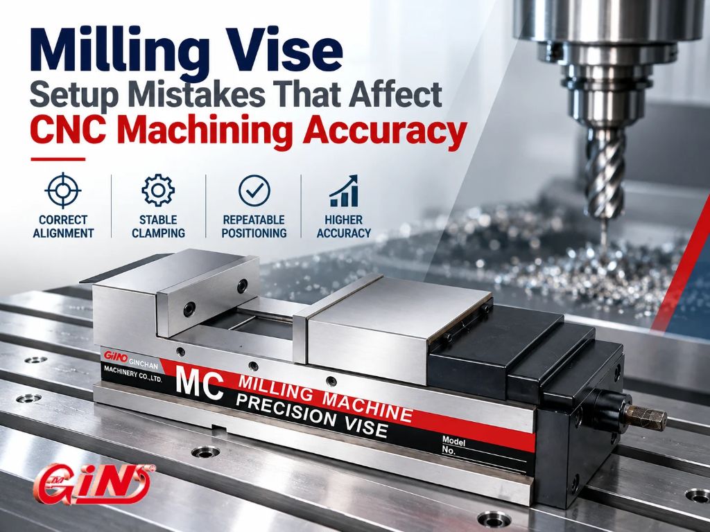
In CNC machining, even a high-precision machine tool cannot consistently produce accurate parts if the workpiece is not properly secured. A small error in milling vise alignment, jaw contact, or clamping pressure can lead to dimensional inaccuracies, poor surface finish, and unnecessary rework.
A milling vise is one of the most commonly used workholding devices in CNC milling operations. However, achieving reliable results depends not only on the vise itself but also on how it is installed, maintained, and used during machining.
For manufacturers handling precision components, understanding common milling vise setup mistakes is essential for improving machining accuracy, reducing setup variation, and maintaining consistent production quality.
This article examines six common setup mistakes, explains how they affect CNC machining results, and provides practical recommendations for improving workholding performance.
1. Incorrect Milling Vise Alignment
The problem: The milling vise is not properly aligned with the machine's intended reference direction.
When a vise is installed on a CNC machine table, its fixed jaw is often aligned parallel to the machine's X-axis. If this alignment is incorrect, workpieces positioned against the fixed jaw may not follow the intended machining coordinate system.
How Does Incorrect Alignment Affect Machining Accuracy?
Depending on the machining setup, misalignment can cause:
- Features machined at unintended angles relative to the workpiece reference.
- Additional setup adjustments and probing requirements.
- Inconsistent results when workpieces are removed and reloaded.
- Errors in operations that assume the fixed jaw is aligned with a machine axis.
How to Prevent It
Use a dial indicator to check the fixed jaw or another specified reference surface while traversing the machine axis.
Adjust the vise position until the alignment meets the requirements of the machining operation, then tighten the mounting fasteners according to the manufacturer's instructions.
Recheck alignment after tightening because the vise may shift slightly during fastening.
Key Takeaway: Vise alignment should be verified against the machining setup's required reference, rather than assumed from the machine table or mounting slots.
2. Chips, Burrs, or Dirt Under the Workpiece
The problem: Foreign material prevents the workpiece from contacting the intended reference surfaces.
Even a small chip trapped between the workpiece and a parallel can affect how the component sits inside the milling vise.
This is particularly important when machining parts requiring accurate flatness, perpendicularity, or dimensional consistency.
What Problems Can Contamination Cause?
- Workpiece tilting or uneven seating.
- Incorrect machining height.
- Inconsistent positioning between parts.
- Surface damage from trapped chips.
- Increased variation during repeated setups.
How to Prevent It
Before clamping a workpiece, clean the vise jaws, parallels, workpiece surfaces, and other contact points.
Inspect the workpiece for burrs, especially after sawing, drilling, or previous machining operations.
Use a suitable deburring method when necessary, taking care not to damage precision reference surfaces.
After clamping, verify that the workpiece is seated correctly against its intended supports.
Key Takeaway: Clean contact surfaces are essential for repeatable workpiece positioning, regardless of the accuracy of the milling vise.
3. Applying Incorrect Clamping Force
The problem: The workpiece is clamped too tightly or without sufficient holding force.
Clamping force is one of the most important factors in CNC workholding.
Excessive force can deform thin-walled or delicate components, while insufficient force may allow the workpiece to move under cutting loads.
What Happens When Clamping Force Is Too High?
- Elastic deformation of thin-walled parts.
- Dimensional changes after unclamping.
- Damage to sensitive workpiece surfaces.
- Distortion of components with limited structural rigidity.
What Happens When Clamping Force Is Too Low?
- Workpiece movement during cutting.
- Vibration or chatter.
- Dimensional inconsistencies.
- Poor surface finish.
- Increased risk of the workpiece becoming dislodged.
How to Prevent It
Select the clamping force according to the workpiece material, geometry, contact area, and expected cutting loads.
For delicate components, consider suitable soft jaws, larger contact areas, or dedicated support arrangements.
Follow the vise manufacturer's recommended operating limits and clamping procedures.
Key Takeaway: The objective is not maximum clamping force, but sufficient and controlled holding force without unacceptable workpiece deformation.
4. Improper Workpiece Seating and Parallel Support
The problem: The workpiece is not properly supported or seated against its intended locating surfaces.
Parallels are commonly used in a milling vise to elevate the workpiece and provide clearance for machining.
However, incorrect parallel selection or poor seating can introduce positioning errors.
Common Mistakes Include
- Using parallels with unsuitable height or condition.
- Allowing chips underneath the parallels.
- Clamping before the workpiece is fully seated.
- Supporting the workpiece unevenly.
- Allowing excessive workpiece overhang without sufficient support.
How to Improve Workpiece Seating
Select parallels that provide appropriate support and machining clearance.
Confirm that both parallels are clean and correctly positioned.
During clamping, use an appropriate seating method when required by the setup, and verify that the workpiece remains in contact with its intended reference surfaces.
For long or irregular components, consider additional support or a different workholding arrangement.
Key Takeaway: Accurate machining requires a stable workpiece reference, not simply a tightly closed vise.
5. Ignoring Jaw Condition and Vise Wear
The problem: Worn or damaged vise components compromise positioning accuracy.
A milling vise may gradually lose its ability to provide consistent workholding if its contact surfaces or moving components become damaged.
Common issues include jaw damage, contamination, excessive mechanical clearance, and deterioration of reference surfaces.
How Can Vise Wear Affect CNC Machining?
- Inconsistent jaw contact.
- Reduced positioning repeatability.
- Workpiece lifting during clamping.
- Uneven clamping pressure.
- Increased setup adjustment time.
How to Prevent It
Inspect the vise regularly for visible damage and abnormal movement.
Pay particular attention to:
- Fixed and movable jaw surfaces.
- Jaw mounting fasteners.
- Guideways and sliding components.
- Clamping screw condition.
- Base and mounting reference surfaces.
Clean and lubricate the vise according to the manufacturer's maintenance instructions.
If accuracy problems persist, verify the vise geometry and mechanical condition before continuing precision production.
Key Takeaway: Routine inspection and maintenance help preserve the positioning performance of a precision machining vise.
6. Using the Wrong Vise Configuration for the Workpiece
The problem: The workholding arrangement does not match the workpiece geometry or machining requirements.
A conventional milling vise can be effective for many CNC operations, but not every component is suitable for the same jaw configuration or clamping method.
For example, a long workpiece may require additional support, while an irregular component may need customized jaws or a dedicated fixture.
When Should the Workholding Setup Be Reconsidered?
- The workpiece cannot be securely supported.
- The required machining surfaces are obstructed by the jaws.
- The component is vulnerable to clamping distortion.
- The setup requires frequent repositioning.
- The available clamping area is insufficient for expected cutting loads.
Depending on the application, possible alternatives include precision modular vises, machinable jaws, specialized fixtures, or other workholding systems.
Key Takeaway: Selecting a suitable vise configuration is as important as correctly installing and operating the vise.
Milling Vise Setup Checklist for CNC Operators
Before starting a machining operation, operators can use the following checklist to identify common workholding problems.
| Inspection Item | What to Verify | Potential Problem Prevented |
|---|---|---|
| Vise Alignment | Fixed jaw follows the required machine reference | Angular positioning errors |
| Contact Surfaces | Jaws, parallels, and workpiece are clean | Incorrect seating |
| Clamping Force | Sufficient holding without excessive distortion | Movement or deformation |
| Parallel Support | Workpiece is correctly seated and supported | Height and positioning variation |
| Vise Condition | Jaws, screw, and guideways are in acceptable condition | Inconsistent clamping |
| Workpiece Geometry | Vise configuration suits the component | Poor support or tool interference |
| Final Verification | Workpiece position and clearance are checked | Setup-related machining errors |
A consistent inspection routine can help reduce avoidable setup variation, particularly in shops processing different components throughout the day.
Gin Tech Milling Vise Solutions for Precision CNC Machining
At Gin Tech, we provide precision machining vise solutions for manufacturers seeking reliable workholding in milling and CNC machining applications.
Our product range includes different vise designs to accommodate varying requirements for machining accuracy, clamping stability, and workpiece positioning.
Precision Mechanical Machine Vise
Gin Tech's Precision Mechanical Machine Vise features an angle-lock mechanism designed to reduce jaw lifting and workpiece tilting during clamping.
Its precision-ground sliding and reference surfaces support accurate positioning in suitable vertical and horizontal milling applications.
Precision Super Vise
The Precision Super Vise incorporates an anti-lift mechanism and is designed for high-precision milling and cutting applications.
Its specified geometric accuracy and horizontal/vertical mounting capability provide additional options for suitable machining setups.
Selecting an appropriate machining vise can help address common workholding problems, but correct installation, clamping procedures, and routine inspection remain essential for maintaining machining accuracy.
Manufacturers should review each product's specifications, available dimensions, and installation requirements before selecting a vise for a particular CNC machine or workpiece.
FAQ: Milling Vise Setup and Accuracy
Q1: Why does a workpiece lift when tightening a milling vise?
Workpiece lifting may occur because of jaw movement, unfavorable clamping geometry, chips beneath the workpiece, or insufficient downward seating force. Check the vise mechanism, contact surfaces, and support arrangement. An appropriate anti-lift or angle-lock vise design can help reduce lifting under suitable operating conditions.
Q2: How often should milling vise alignment be checked?
Alignment should be verified whenever the vise is installed, repositioned, or disturbed. Additional checks may be necessary after a collision, maintenance work, or when machining results indicate a positioning problem. The required alignment tolerance depends on the workpiece and machining operation.
Q3: Why do machined dimensions change after removing a workpiece from the vise?
The workpiece may have experienced elastic deformation from clamping pressure or residual stresses released during machining. Thin-walled components are particularly susceptible. Review clamping force, support conditions, machining sequence, and workpiece material before adjusting the machining program.
Conclusion: Improve CNC Accuracy Through Better Milling Vise Setup
A precision milling vise is an essential part of accurate CNC machining, but its performance depends on proper installation and workholding practices.
Incorrect alignment, contaminated reference surfaces, excessive clamping force, improper workpiece support, vise wear, and unsuitable clamping configurations can all contribute to machining errors.
By establishing a consistent setup inspection routine, manufacturers can reduce avoidable positioning problems, improve machining consistency, and maintain more reliable production results.
Find the Right Milling Vise for Your CNC Application
Gin Tech offers precision milling vises and machining vise solutions designed for different CNC workholding requirements.
Whether you need to improve clamping stability, reduce workpiece lifting, or select a vise for a particular machining application, our team can help you evaluate suitable options.
Contact Gin Tech to discuss your workpiece dimensions, material, machining conditions, and accuracy requirements.
Explore our Precision Mechanical Machine Vise and Precision Super Vise to find a workholding solution suited to your manufacturing needs.